HOME Information DrayTek Blog Switch STP introduction and how to set up STP on VigorSwitch
STP introduction and how to set up STP on VigorSwitch
DrayTek VigorSwitches support STP/RSTP/MSTP which allows switch redundancy as well as preventing loops at the same time. This article introduces how STP works and how to set up STP on a DrayTek VigorSwitch. A typical topology where STP can be used is shown here where we have 4 VigorSwitches and a redundant path between the switches for failover.
STP
Spanning Tree Protocol(STP) is a management protocol that works on Layer 2 of the OSI model. The main purpose of STP is to detect and prevent the switch from the Broadcast Strom caused by using the Redundant Path mechanism. However, the network convergence process of STP is a slow process. RSTP speeds up the network convergence process. But RSTP has a flaw same as STP, that is, Load Balance can not be implemented among VLANs. And MSTP not just fasts the network Convergence, MSTP implements load balancing among VLANs.
Note: The process of each port to change the status, we call it Convergence.

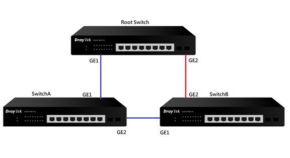
When STP is enabled, the redundant path in the network topology shown by the red line will be blocked to prevent loops. If one of the other links shown be the blue lines goes down, then the redundant link (red line) will come up to provide continuity in the switch network.
RSTP
Rapid Spanning Tree Protocol (RSTP) is an enhancement of STP which responds to Bridge Protocol Data Units (BPDU) from the direction of the root while STP cannot. It provides rapid convergence of the spanning tree.
MSTP
Multiple Spanning Tree Protocol (MSTP) is a further enhancement to RSTP which enables VLANs to be grouped into a spanning-tree instance, providing multiple forwarding paths for data traffic, and enabling load balancing.
BPDU
Bridge Protocol Data Unit (BPDU) contains the information to configure and maintain the spanning-tree topology, includes the port attribute, MAC address, priority, and path cost. Vigor Switches running STP, RSTP, MSTP exchange BPDUs to calculate a loop-free topology. During the deployment of a spanning tree protocol, the edge ports do not participate in the calculation of the spanning-tree and able to transition from the Disable status to the Forward status immediately. This way, the edge ports could prevent the switches from re-calculate due to frequent online and offline, to improve network reliability.
STP settings on DrayTek VigorSwitch
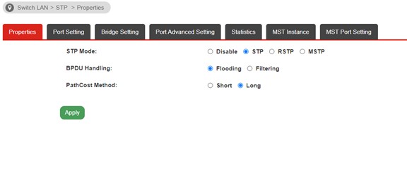
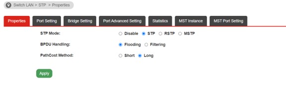
a. Switch LAN >> STP >> Properties
BPDU Handing
• Filtering: Filter the BPDU packets when STP is disabled
• Flooding: Flood the BPDU packets when STP is disabled
PathCost Method
• Short: Specifies that the default port path costs are within the range: 1~65,535
• Long: Specifies that the default port path costs are within the range: 1~200,000,000
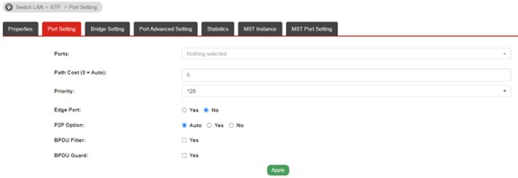
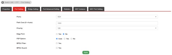
b. Switch >> STP >> Port Setting
• Path Cost: Path Cost is the cost of transmitting a frame to Root Switch through that port. Select "O" means the value will be specified by the switch.
• Priority: Specify a priority value for the port. The smaller the value, the higher the priority to becoming the Root Port.
• Edge Port: If the connects to an end device such as PC, printer you may enable Edge Port to speed up the STP calculation.
• BPDU Filter: Enable for set the port stops to send/receive BPDU packets.
• BPDU Guard: Enable for shutdown the port when receives any BPDU packets, for protect your switch.
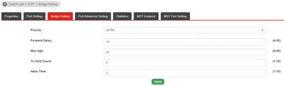
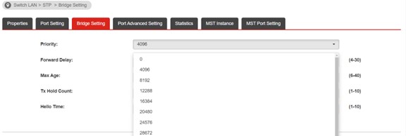
c. Switch LAN >> STP >> Bridge Settings
• Priority: Known as Bridge ID. The smaller the value, the higher the priority to be the Root Switch.
• Forward Delay, Max Age, Tx Hold Count, Hello Time: These settings are irrelevant to configure for the topology. Please check the explanation on User Guide.
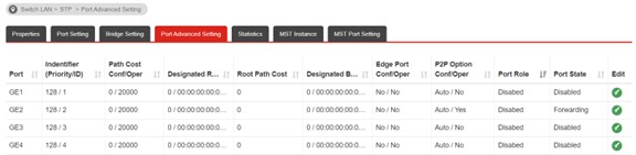
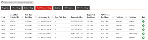
d. Switch LAN >> STP >> Port Advanced Settings >> Port Role
We could check the Port Role for troubleshooting on STP.
• Root: The port that connects to the Root Switch, or the port that is closest to the Root Switch.
• Designated: If the port isn't selected as Root Port, it become Designated Port. And each switch only have one Desinated Port, used for transfer general date.
• Alternate: If the port isn't selected as Root Port/Designated Port, it becomes Alternate Port, which is a backup port for Designated Port.
Election Rule of STP
Root Switch:
The lower the value(Bridge ID), the higher the priority
Root Port:
The port has lowest of Root Cost, becomes the Root Port.
Root Cost means the path cost that the port reaches to the Root Switch.
Example:
SwitchA GE1 -> GE1 Root Switch => Root Cost:1
SwitchB GE1 -> GE2 SwitchA GE1 -> GE1 Root Switch => Root Cost:2. For SwitchB, GE1 is the Root Port, because red line is not up.
How to set up STP on VigorSwitch
We will use the topology shown in the diagram below to show the steps to set up STP in on VigorSwitches.
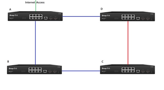
In this switching network the red link will be blocked to prevent a loop. If the BC link goes down, the CD link will come up to allow Switch to continue having internet access. In conclusion, Switch A should be the Root Switch.
Phase1: Set up STP Root Switch
a. Go to Switch LAN >> STP >> Properties, and enable STP on all VigorSwitches.
b. Go to Switch LAN >> STP >> Bridge Settings
• Set up the lowest value of Priority on Switch A such as 4096. (The lower the value, the higher the priority)
• Set up the highest value of Priority on Switch C such as 12288
• Set up default value of Priority on Switch B, Switch D such as 8192
After about 1 minutes STP caLculation, STP is working now. We could check the Port Role at Switch LAN >> STP >> Port Advanced Setting
• On SwitchA(Root), you can see the ports that connect to other switches is Root Port and the Port State is Forwarding.
• On other switches, the port connects to the Root Swich that show Root as Port Role
Set up STP path
After completing phase1 configuration, STP will now be working on the network, but we haven't configured the path to meet the topology as shown in our diagram. The following steps will show you how to set up the STP path
a. Go to Switch LAN >> STP >> Port Setting on SwitchC
• Select the port that connects to Switch D
• Set up the path cost that must higher than other ports such as 100
• Same steps should apply to the port on Switch D which connects to Switch C
b. After configuring Path Cost, go to Switch >> STP >> Port Advanced Setting, we can see the Port Role is Alternate and the Port State os Discarding on GE4
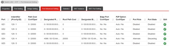
c. After the steps above, the STP meets the topology now.