HOME Information DrayTek Blog Switch Introduction to Stacking
Introduction to Stacking
Stacking is a method of binding multiple units of switches so that they can act as a single logical switch. The VigorSwitch 2282x now supports stacking. With stacking enabled, up to 4 VigorSwitch 2282x units can be grouped together, offering centralized management through a single IP address. This not only simplifies network configuration and monitoring, but also enhances scalability and flexibility. Network administrators can expand capacity by adding switches to the stack without disrupting the existing setup.
Additionally, stacking provides improved redundancy—if the master unit fails, another switch in the stack can take over automatically to maintain network continuity.
Support Model and firmware version:
VigorSwitch G/P2282x version 2.10.1 and above
Stacking Components
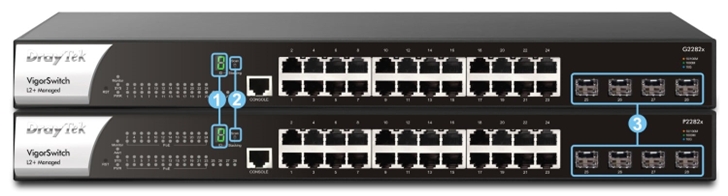
1. Monitor
The monitor will display the Device ID, status and error code.
2. Stacking button
Quickly install without login via the stacking button operation and reduce the effort in scaling up the numbers of available ports.
3. Stacking port
VigorSwitch uses 10G SFP+ ports as the stacking ports to connect between the units, requiring a 10G link for operation. G model and P model are are allowed to establish Stacking and display PD for the ports on the P model.
Enable Stacking
Press and hold for 1~4 second, we can see the bottom right LED on. The system will establish the stacking environment to elect which device will be the Primary automatically. ID starts from 0 to F is the priority from the highest to the lowest. Primary ID is always 0.
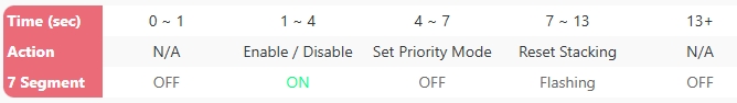
Button Behavior:
Modify Priority
1. If you wish to modify the priority, press and hold for 1~4 seconds to disable the stacking. It’s unable to enter set priority mode when Stacking is enabled.
2. When Stacking is disabled, press and hold 4~7 seconds to enter Set Priority Mode.
3. The switch will enter the priority menu. Press and hold the button again, the menu will display the priority ID from F → 0 → 1 → 2 → ∙ ∙ ∙ → E while holding the button.

4. Release the button to choose the priority when it displayed the desired ID number on the monitor.
5. Enable the stacking back again and wait for the switches to apply the priority. It should be good to work with the ID number you just configured.
Adding a New Unit
It’s simple to add a new unit in a running stacking environment. Connect a new switch unit to any available stacking ports and perform the steps to enable stacking. The Primary will detect and add the new unit into the stacking environment.
Please note that one stacking environment can allow 4 units (1 Primary + 3 Slots) at most.
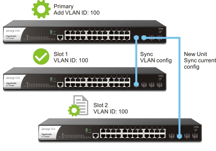
Configuration Sync
Stacking environment allows administrators to manage the settings and access different units by the primary WebUI page to achieve single IP management.
1. When setting up, for example, VLAN ID 100 on the primary, the VLAN 100 setting will also sync to all the slot units.
2. When adding new device, the current configuration in the stacking environment will sync to the new unit.
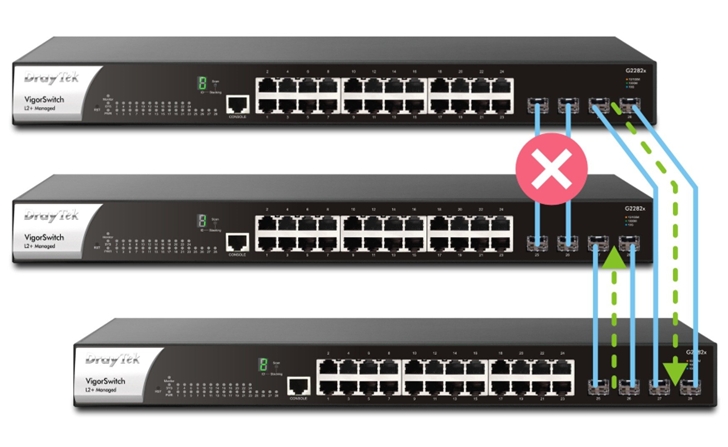
Reliability
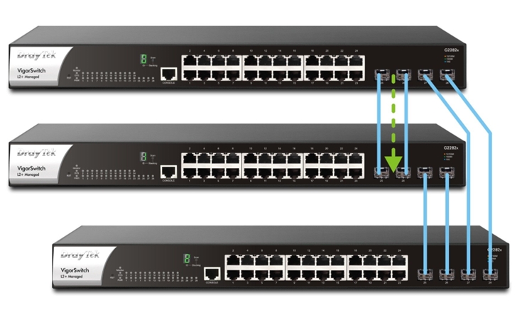
Here we use a Ring topology for example. If the link from primary to slot#1 is down, Stacking environment detects the failure and forward the traffic via slot#2. The traffic will take another route to reach the destination and maintain the reliability.
Seven-segment Display
The seven-segment display on the VigorSwitch provides stacking status:
1. Successful stacking: Displays the Device ID.
2. Unstable stacking: Blinks until it reaches a stable state.
3. Failed stacking: Alternates between ‘r’ and an error ID, indicating the reason:
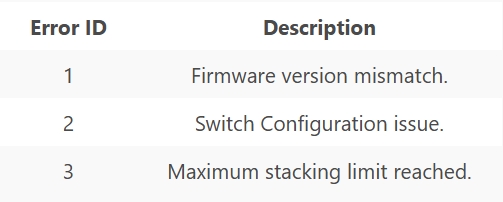
For example, if an r-2 error occurs while establishing the stacking, the monitor will prompt the r-2 error code as below:

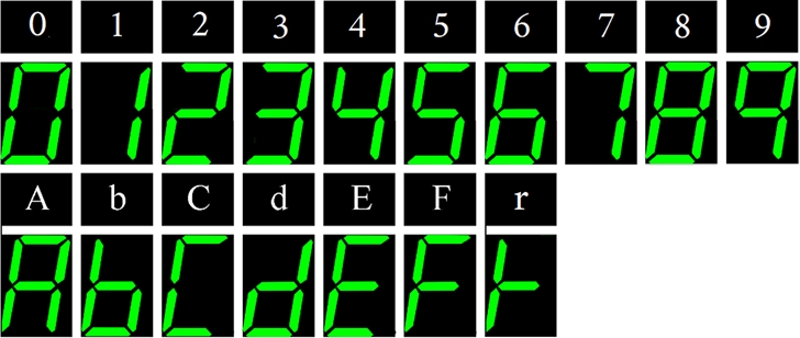
Here’s the example of numbers and English letters A to F and r on the seven-segment display for reference.
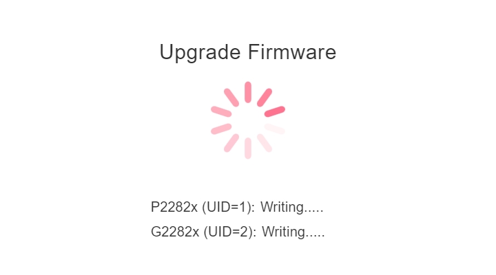
Firmware Upgrade
Firmware upgrades only need to be performed on the primary unit. Once the upgrade is initiated, all switches within the stacking environment will be automatically updated as well, ensuring that the firmware versions remain consistent across all devices.